- 您现在的位置:买卖IC网 > Sheet目录865 > ISL8206MIRZ-T (Intersil)IC BUCK SYNC ADJ 6A 15QFN
�� �
�
�ISL8204M,� ISL8206M�
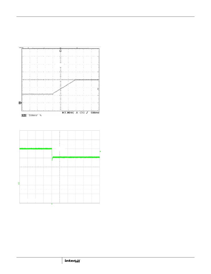
�If� the� output� is� pre-biased� to� a� voltage� above� the� expected� value�
�(as� shown� Figure� 22),� neither� MOSFET� will� turn� on� until� the� end� of�
�the� soft-start,� at� which� time� it� will� pull� the� output� voltage� down� to�
�the� final� value.� Any� resistive� load� connected� to� the� output� will� help�
�pull� down� the� voltage� (at� the� RC� rate� of� the� R� of� the� load� and� the� C�
�of� the� output� capacitance).�
�V� OUT�
�FIGURE� 21.� PRE-BIASED� START-UP�
�V� OUT�
�500mV/DIV�
�FIGURE� 22.� PRE-BIASED� START-UP� -� OVERCHARGED�
�to� delay� the� soft-start� until� the� V� IN� supply� is� ready� (see� “Input�
�Voltage� Considerations”� on� page� 13).�
�If� ISL8204M,� ISL8206M� is� disabled� after� soft-start� (by� pulling�
�COMP/EN� pin� low),� and� afterwards� enabled� (by� releasing� the�
�COMP/EN� pin),� then� the� full� initialization� (including� OCP� sample)�
�will� take� place.� However,� there� is� no� new� OCP� sampling� during�
�overcurrent� retries.� If� the� output� is� shorted� to� GND� during� soft-�
�start,� the� OCP� will� handle� it,� as� described� in� the� next� section.�
�Overcurrent� Protection� (OCP)�
�The� overcurrent� function� protects� the� converter� from� a� shorted�
�output� by� using� the� low� side� MOSFET� ON-resistance,� r� DS(ON)� ,� to�
�monitor� the� current.� A� resistor� (R� SET� )� programs� the� overcurrent�
�trip� level.�
�This� method� enhances� the� converter's� efficiency� and� reduces�
�cost� by� eliminating� a� current� sensing� resistor.� If� overcurrent� is�
�detected,� the� output� immediately� shuts� off.� It� cycles� the� soft-start�
�function� in� a� hiccup� mode� (2� dummy� soft-start� time-outs,� then� up�
�to� one� real� one)� to� provide� fault� protection.� If� the� shorted�
�condition� is� not� removed,� this� cycle� will� continue� indefinitely.�
�Following� POR� (and� 6.8ms� delay),� the� ISL8204M,� ISL8206M�
�initiates� the� overcurrent� protection� sample� and� hold� operation.�
�The� low� side� gate� driver� is� disabled� to� allow� an� internal� 21.5μA�
�current� source� to� develop� a� voltage� across� R� SET� .� The� ISL8204M,�
�ISL8206M� samples� this� voltage� (which� is� referenced� to� the� PGND�
�pin)� at� the� ISET� pin,� and� holds� it� in� a� counter� and� DAC�
�combination.� This� sampled� voltage� is� held� internally� as� the�
�overcurrent� set� point,� for� as� long� as� power� is� applied,� or� until� a�
�new� sample� is� taken� after� coming� out� of� a� shut-down.�
�The� actual� monitoring� of� the� low� side� MOSFET� ON-resistance�
�starts� 200ns� (nominal)� after� the� edge� of� the� internal� PWM� logic�
�signal� (that� creates� the� rising� external� low� side� gate� signal).� This�
�is� done� to� allow� the� gate� transition� noise� and� ringing� on� the�
�PHASE� pin� to� settle� out� before� monitoring.� The� monitoring� ends�
�when� the� internal� PWM� edge� (and� thus� low� side� gate� signal)� goes�
�low.� The� OCP� can� be� detected� anywhere� within� the� above�
�window.�
�If� the� converter� is� running� at� high� duty� cycles,� around� 75%� for�
�600kHz� operation,� then� the� low� side� gate� pulse� width� may� not� be�
�wide� enough� for� the� OCP� to� properly� sample� the� r� DS(ON)� .� For� those�
�cases,� if� the� low� side� gate� signal� is� too� narrow� (or� not� there� at� all)�
�for� 3� consecutive� pulses,� then� the� third� pulse� will� be� stretched�
�and/or� inserted� to� the� 425ns� minimum� width.� This� allows� for�
�OCP� monitoring� every� third� pulse� under� this� condition.� This� can�
�introduce� a� small� pulse-width� error� on� the� output� voltage,� which�
�will� be� corrected� on� the� next� pulse;� and� the� output� ripple� voltage�
�will� have� an� unusual� 3-clock� pattern,� which� may� look� like� jitter.�
�I� PEAK� =� --------------------------------------------�
�If� V� IN� for� the� synchronous� buck� converter� is� from� a� different�
�supply� that� comes� up� after� P� VCC� ,� the� soft-start� will� go� through� its�
�cycle,� but� with� no� output� voltage� ramp.� When� V� IN� turns� on,� the�
�output� will� follow� the� ramp� of� the� V� IN� from� zero� up� to� the� final�
�expected� voltage� (at� close� to� 100%� duty� cycle,� with� COMP/EN� pin�
�The� overcurrent� function� will� trip� at� a� peak� inductor� current�
�(I� PEAK� )� determined� by� Equation� 2:�
�2� � I� SET� � R� SET�
�r� DS� (� ON� )�
�(EQ.� 2)�
�>4V).� If� V� IN� is� too� fast,� there� may� be� excessive� inrush� current�
�charging� the� output� capacitors� (only� the� beginning� of� the� ramp,�
�from� zero� to� V� OUT� matters� here).� If� this� is� not� acceptable,� then�
�consider� changing� the� sequencing� of� the� power� supplies,� sharing�
�the� same� supply,� or� adding� sequencing� logic� to� the� COMP/EN� pin�
�12�
�where:�
�I� SET� is� the� internal� I� SET� current� source� (21.5μA� typical).�
�R� SET� is� equivalent� resistance� between� ISET� and� PGND� pins.�
�FN6999.3�
�July� 26,� 2012�
�发布紧急采购,3分钟左右您将得到回复。
相关PDF资料
JF04R0R051020AA
CABLE ASSY HI SPEED 51POS 20CM
JJC0E338MSEJBN
CAP SUPER 3300F 2.5V SCREW
JJD0E408MSEG
CAP SUPER 4000F 2.5V SCREW
JJL0E268MSEG
CAP SUPER 2600F 2.5V SCREW
JMK042BJ103KC-F
CAP CER 10000PF 6.3V X5R 01005
JUMT1476MHD
CAP SUPER 47F 2.7V RADIAL
JUWT1476MHD
CAP SUPER 47F 2.7V RADIAL
JWK316BJ106KD-T
CAP CER 10UF 6.3V 10% X5R 0612
相关代理商/技术参数
ISL8216MEVAL1Z
功能描述:电源管理IC开发工具 ISL8216M EVALUATION BOARD 1 - 25 Ld HDA - RoHS COMPLIAN
RoHS:否 制造商:Maxim Integrated 产品:Evaluation Kits 类型:Battery Management 工具用于评估:MAX17710GB 输入电压: 输出电压:1.8 V
ISL8216MIRZ
制造商:Intersil Corporation 功能描述: 制造商:Intersil Corporation 功能描述:STAND ALONE HIGH VOLTAGE ANALOG DC/DC STEP DOWN POWER SUPPLY - Rail/Tube
ISL8216MIRZ-T
制造商:Intersil Corporation 功能描述:STAND ALONE HIGH VOLTAGE ANALOG DC/DC STEP DOWN POWER SUPPLY - Tape and Reel
ISL8225M
制造商:INTERSIL 制造商全称:Intersil Corporation 功能描述:Dual 15A/Single 30A Step-Down Power Module
ISL8225M_13
制造商:INTERSIL 制造商全称:Intersil Corporation 功能描述:Dual 15A/Single 30A Step-Down Power Module
ISL8225MEVAL2Z
功能描述:电源管理IC开发工具 90A,1.2Vout Eval Brd w/ 3 ISL8225M Modul.
RoHS:否 制造商:Maxim Integrated 产品:Evaluation Kits 类型:Battery Management 工具用于评估:MAX17710GB 输入电压: 输出电压:1.8 V
ISL8225MEVAL3Z
功能描述:电源管理IC开发工具 ISL8225M EVAL
RoHS:否 制造商:Maxim Integrated 产品:Evaluation Kits 类型:Battery Management 工具用于评估:MAX17710GB 输入电压: 输出电压:1.8 V
ISL8225MEVAL4Z
功能描述:电源管理IC开发工具 Dual 15A Output Eval Board
RoHS:否 制造商:Maxim Integrated 产品:Evaluation Kits 类型:Battery Management 工具用于评估:MAX17710GB 输入电压: 输出电压:1.8 V